Knowledge Base / RF Engineering
Why Predictive RF Design Isn't Enough on Its Own
June 2026
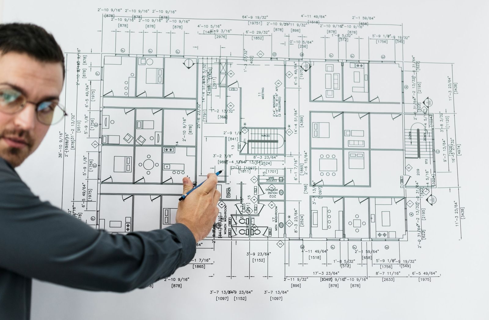
Predictive RF design has become standard practice for a reason: it lets an engineer model access point placement, channel planning, and expected coverage before a single access point goes on a wall. Tools like Ekahau's planner take an architectural floor plan, apply attenuation values for walls, doors, and structural elements, and generate a heatmap that looks conclusive. For budgeting, procurement, and early-stage cable planning, that model is genuinely useful.
The trouble starts when a predictive model is treated as the finished product rather than a first draft. A floor plan tells you where the walls are supposed to be — not what they're actually built from, whether a mechanical room got re-purposed into dense server racking after the drawings were filed, or how much metal shelving, machinery, or signage has been added since the building was last surveyed. Every one of those variables changes how radio frequency actually behaves in that space, and none of them show up in a CAD file.
Where the Model and Reality Diverge
RF propagation is sensitive to material composition in ways that are difficult to fully specify in advance. Low-e glass, foil-backed insulation, and metal wall studs can attenuate a signal far more aggressively than a generic drywall value assumes. Concrete tilt-up construction common in warehouses and distribution centers behaves differently depending on rebar density. Multipath reflection off metal racking or equipment can create constructive and destructive interference patterns that a planning tool's ray-tracing approximates but cannot fully predict without measuring the actual environment.
Device behavior adds another layer. A predictive model typically assumes a reasonable client radio and antenna performance. In practice, handheld scanners, mobile carts, badge readers, and IoT sensors often have far weaker antennas and lower transmit power than a laptop or smartphone, meaning the client experience can be meaningfully worse than what the heatmap implies — particularly at the edges of a cell where roaming decisions happen.
Why the Validation Survey Is the Part That Actually Proves the Design
An active and passive validation survey closes that gap. Walking the space with calibrated survey hardware after access points are mounted measures what is actually happening on the RF spectrum in that building, with its actual construction, actual inventory, and actual interference sources — not the assumed version. Active surveys measure real throughput, roaming behavior, and authentication performance from an associated client. Passive surveys map coverage and interference without associating, giving a clean picture of the RF noise floor and co-channel contention across every access point in range.
Where the validation survey turns up a gap — a dead zone behind a newly installed piece of equipment, unexpected co-channel interference from a neighboring tenant, or a roaming boundary that doesn't behave the way the model predicted — that's the point where a design gets adjusted before it becomes a support ticket. Catching it during validation costs an access point move or a channel re-plan. Catching it after go-live costs downtime, an emergency site visit, and a much harder conversation with whoever depends on that network functioning.
The Right Sequence
The engagements that hold up best in the field follow the same order every time: predictive design to plan intelligently and budget accurately, deployment guided by that plan, and then active and passive validation to confirm the as-built environment performs the way it was designed to. Skipping the last step doesn't save time so much as defer the discovery of every problem the model couldn't see — to a moment when it's far more disruptive to fix.
Ready to talk through your space?
Tell us about your facility and we'll scope the right survey and design approach — no obligation.
Start a Project Inquiry